CASE 02 · SELECTED WORK

Turning two tube measurements into a complete print-ready clamp set

A guardrailed sizing workflow links user measurements to an Excel design table, a SolidWorks assembly, and 19 STL outputs per recorded variant.
Alexzander Davidson

Technical product portfolio

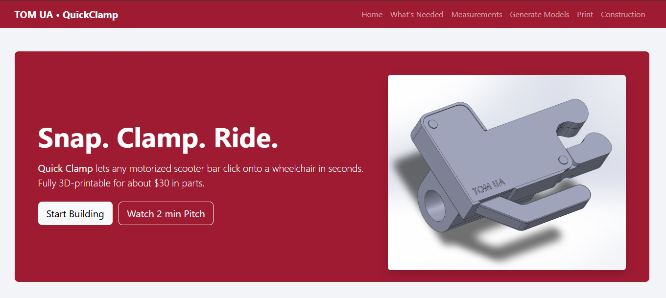
QuickClamp project home page with a clamp render and build workflow
Role
Product and CAD workflow lead
Team
Alexzander Davidson · Later QuickClamp collaborators
Dates
2025
Status
Working internal and open-source project workflow
Methods
SolidWorks · Excel design table · STL export · web workflow
Disclosure
AI-assisted implementation disclosed

The system problem

01

Customization cannot depend on manually rebuilding CAD every time.

Wheelchair and scooter frames vary. A fixed clamp cannot serve that variation, while manual CAD editing makes every new fit expensive and dependent on the original designer.

I reduced the product interface to two user-supplied diameters. Those values enter a design table, drive a parameterized SolidWorks assembly, and produce a complete set of printable files.

The implementation boundary matters: the web and export code was AI-assisted. This case demonstrates product definition, CAD parameterization, workflow orchestration, and validation. It is not presented as proof of unaided Python authorship.
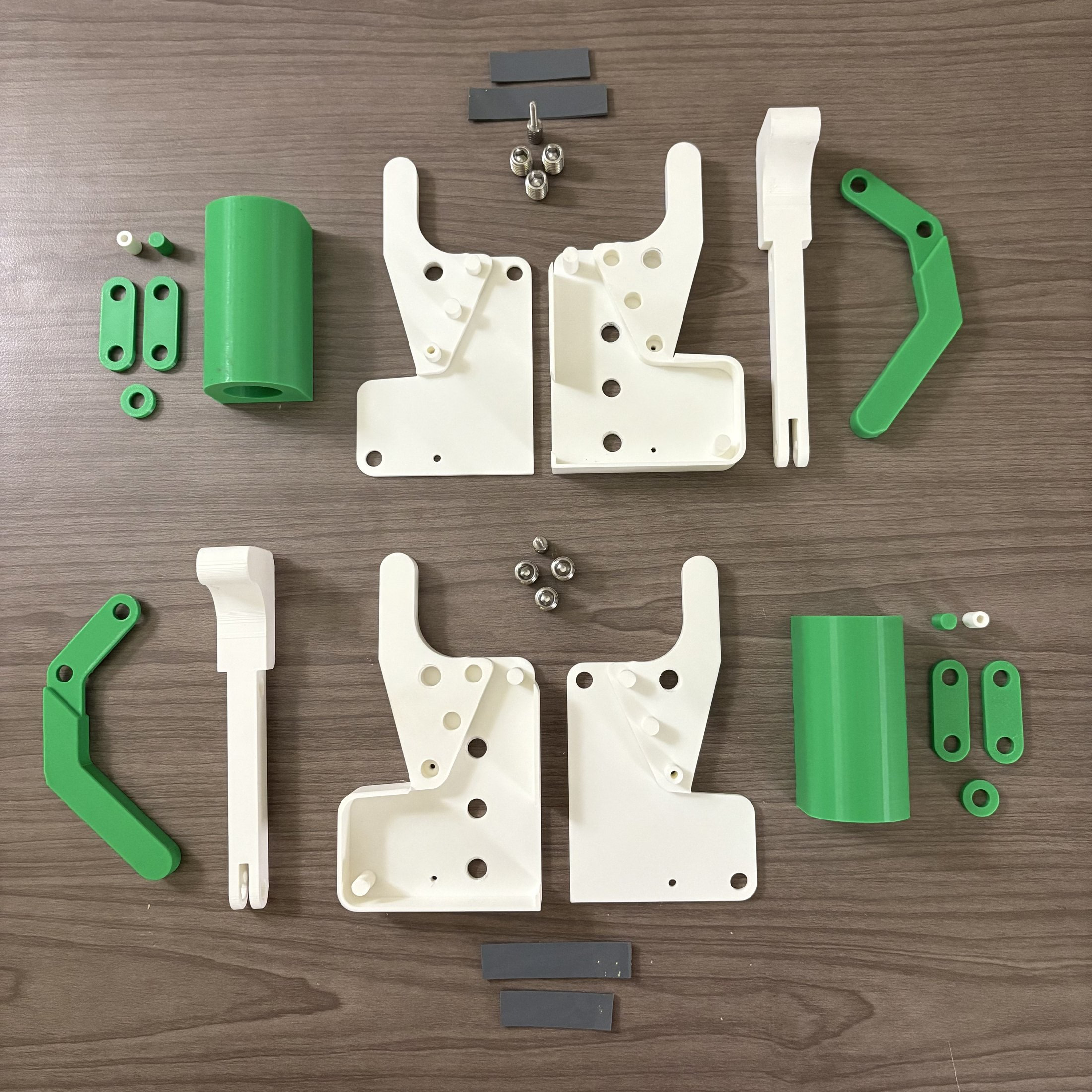
Exploded QuickClamp assembly showing the complete part set and fasteners
FIG 01The output is not one mesh. It is a coordinated assembly whose parts must change together.

Architecture

02

Two inputs, one controlled rebuild, nineteen files.

Artifact-verified

Parametric clamp generation workflowTwo tube-diameter inputs are validated, written to a SolidWorks design table, used to rebuild an assembly, and exported as a complete set of nineteen STL files.01 · INPUT18–32 mm wheelchair12.7–33.02 mm scooter02 · DESIGN TABLETwo controlled variablesMillimeters or inches03 · REBUILDParameterized assemblySolidWorks regeneration04 · OUTPUT19 STL files / variantNamed and packaged
  1. 01 · InputWheelchair 18–32 mm
    Scooter 12.7–33.02 mm
  2. 02 · Design tableTwo controlled variables
    Millimeters or inches
  3. 03 · RebuildParameterized assembly
    SolidWorks regeneration
  4. 04 · Output19 STL files per variant
    Named and packaged
FIG 02Two measured diameters move through validation, a design table, assembly rebuild, and a complete print-ready output set.

Requirements

03

The workflow rejects geometry it cannot honestly support.

SYS-01

Accept millimeter and inch inputs

Implemented
SYS-02

Constrain wheelchair diameter to 18–32 mm

Implemented
SYS-03

Constrain scooter diameter to 12.7–33.02 mm

Implemented
SYS-04

Update a canonical two-variable design table and rebuild the assembly

Implemented
SYS-05

Export, group, name, and package a complete set of STL files
Implemented

Workflow

04

The user sees measurements and outputs, not the CAD internals.

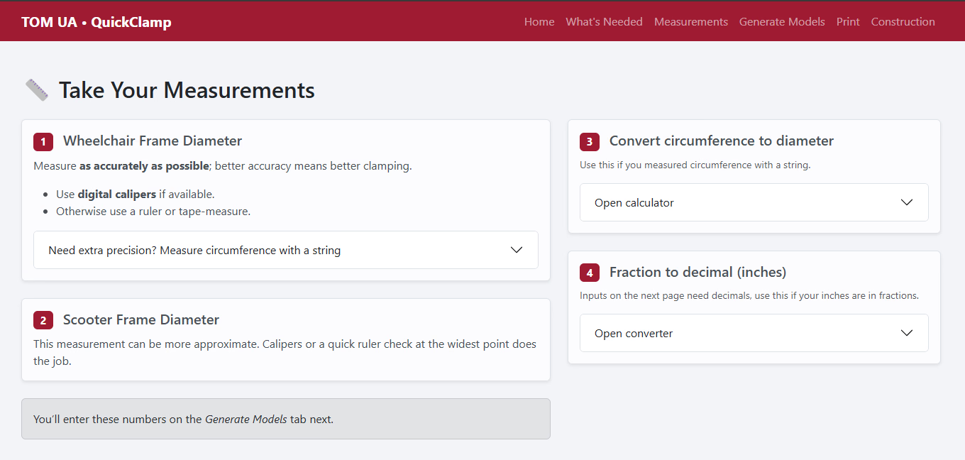
QuickClamp page explaining wheelchair and scooter diameter measurements and conversions
FIG 03Measurement is treated as a product step. The interface supports calipers, a circumference conversion, and fractional-inch conversion.
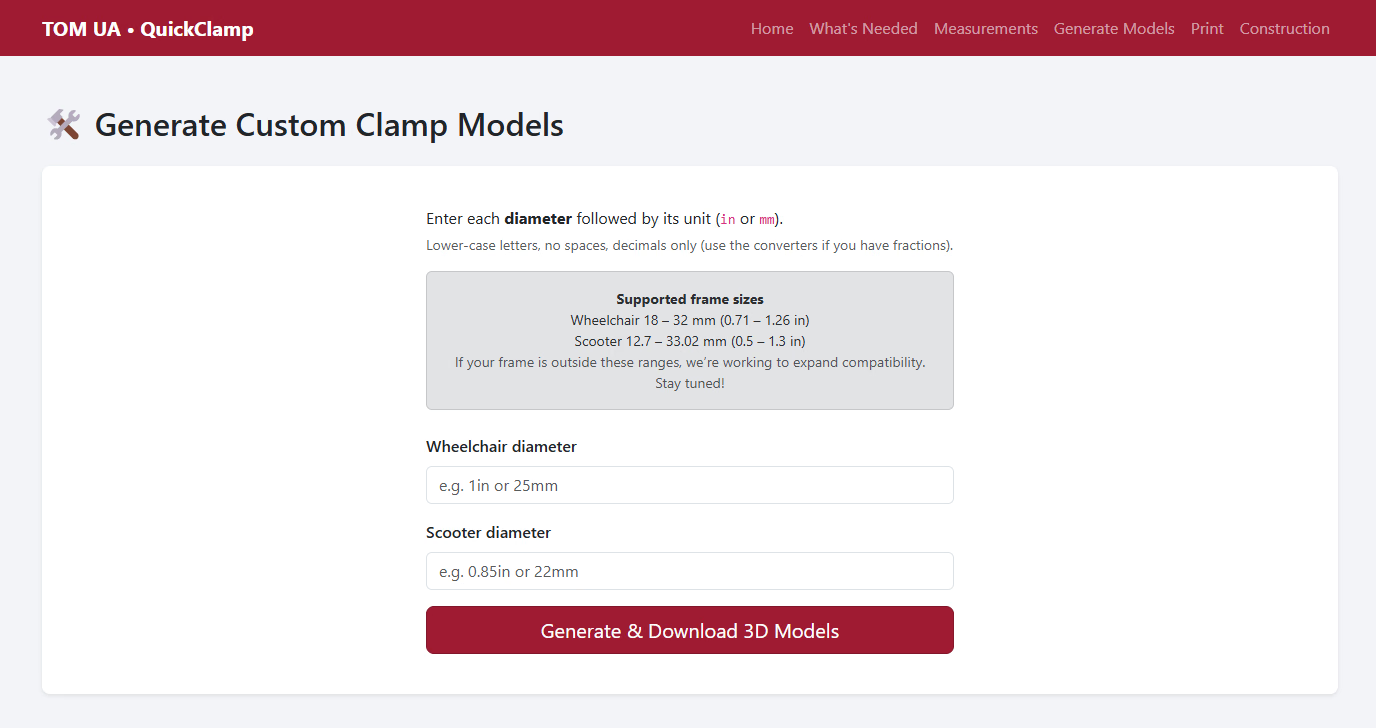
QuickClamp generator with two diameter input fields and a generate button
FIG 04The smallest useful interface is two explicit diameters with units and bounded ranges.

Decisions

05

Guardrails are part of the product.

01

Two inputs instead of an open CAD editor

The end user needs a fit path, not access to the model’s entire parameter space.

02

Explicit range validation instead of “universal” generation

Wheelchair inputs are constrained to 18–32 mm and scooter inputs to 12.7–33.02 mm in the recovered workflow.

03

One packaged output instead of loose files

Each generated configuration is named, grouped, and zipped so the assembly remains coherent.
Print path

06

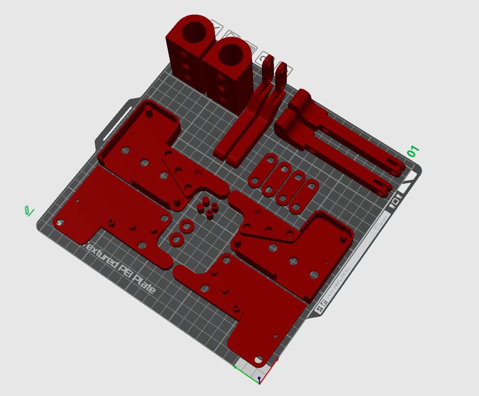
The workflow includes fabrication preparation.

QuickClamp components arranged on a 3D printer build plate
FIG 05Print orientation and part grouping connect the digital variant to a physical build.
FIG 06A five-second derivative of the first-party print time-lapse. The original remains outside the public repository.

Evidence ledger

07

The local artifacts establish what the system produced.

Achieved · individual

Verified 2026-09-25

The source workflow accepts wheelchair diameters from 18–32 mm and scooter diameters from 12.7–33.02 mm

achieved

Achieved · individual

Verified 2026-09-25

Each recorded export folder contains 19 STL files

achieved

Achieved · individual

Verified 2026-09-25

The local artifact archive contains 30 generated output directories across several tube-diameter combinations

achieved

Boundary

08

A working internal tool is not the same as a maintained public service.

Constraint

Support tube variation without manual remodeling

Decision

Guardrail two measurements and drive a parameterized assembly

Evidence

30 recorded output folders; 19 STL files in each audited folder

Next test

Identify physically tested variants and harden the Windows/SolidWorks automation path

OPEN-01

Which recorded variants completed physical fit testing

Open
OPEN-02

Production reliability of the Windows/SolidWorks automation path

Open
OPEN-03

A public-safe, maintained deployment of the generator

Open

Selected evidence

09

The product lineage is publicly documented.

A custom product becomes more useful when the customization itself becomes a system.